

THE SKIPPER D FIELD GUIDE
Know what the next
move is for.
A practical map of the workspace: what each part does, when to use it, and what to check before material meets tool.
01 / Start with the part, not the connection.
You can draw and edit without a machine connected. The viewport is the design workspace; the Outliner organizes your objects, and Properties shows settings for the current selection. Editor areas can be rearranged so the controls you use are close at hand.
Choose millimetres or inches for display and input. Dimensions are stored internally in millimetres. Save a .skipper project to keep the design and its machining information together. A project is not the same thing as exported G-code.
02 / Build geometry at the size you mean.
Use rectangles, ellipses, lines, triangles, freehand and vector tools to assemble a layout. Exact-size fields change physical dimensions; position and scale snapping serve different purposes. A chosen pivot determines the reference for scaling and rotation.
Groups organize related objects. Check enabled, visible and locked states rather than assuming a hidden object is excluded from execution. Protected no-go regions are separate from centroids and provide a way to mark areas that should not be cut.
Working with PCB layouts?
DXF export transfers drawn outlines for workflows such as matching board dimensions in KiCad. It represents the geometry as drawn—not an invisible adjustment for the cutter's finished boundary. Check units and placement after import.
03 / A bit describes a tool. A preset describes a job.
Bit definitions hold physical identity: name, icon, width, suitable material, flute count and bit type. A laser's width represents its beam size. Feed, depth, power and cooling choices belong to the machining mode, not to an ever-changing tool definition.
Pick the correct bit and set the recipe in Properties. Saved Linear presets include hidden feature values, feature switches and foldout states. The main mode On/Off state is not part of the preset. Saving beside a selected preset updates it directly; its editor handles naming and detailed changes.
Material labels are organizational information, not an automatic guarantee of safe speeds and feeds. Use parameters appropriate to the actual cutter, stock, machine rigidity and workholding.
04 / Linear: follow an outline or work a surface.
Outline follows the geometry with the selected on-line, inside or outside placement. Surface works an enclosed region with the available surface strategies. Direction matters: inspect the chosen cut direction rather than relying on the winding of a sketch alone.
In CNC mode, set start and target depth, depth per pass, cutting and plunge feeds, spindle settings and the editable Passes count. Target depth is entered as a positive downward depth. Passes repeats the complete operation; it is not the same as dividing the depth into layers.
Optional techniques
- Spring passes: repeat a pass at its existing depth without going deeper.
- Air cooling: the current cooling-pause controls retract and wait. They do not imply an air-valve output.
- Liquid cooling: uses the selected controller coolant output, if your machine supports it.
- Trochoidal channeling and ramping: specialized outline strategies. Diameter, spacing, feeds and waste side need intentional setup.
- Moonwalking and halfpiping: additional motion patterns for particular jobs, not universal improvements.
- N Mode: uses its own depth increment, advances slowly along a local segment, backtracks at depth, pauses and returns to the cutting front. It is an alternative to the other special patterns, not a guarantee against tool loading or chip welding.
Feature switches reveal their foldouts. Settings remain saved when a feature is off, so returning to a recipe does not mean rebuilding it.
05 / Pecking: finish the local work.
Pecking approaches a path through repeated plunge cuts. Set depth per peck, feed, spacing and relevant pauses. Outline placement can be on, inside or outside the original line. Bit Width comes from the selected cutter; Additional Width extends the cut according to that placement, and Total Width shows the result.
Plan plunge spacing for your cutter and material. Small increments increase machining time. A recipe suitable for one machine or material should not be assumed suitable for another.
06 / The drawing is the bevel profile.
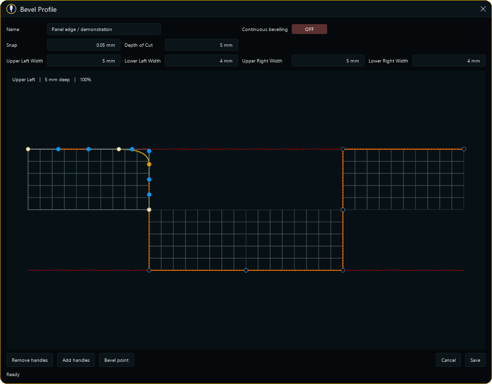
The bevel editor represents a cross-section of the intended edge, not a decorative curve. Start from the workpiece/channel shape, place points on the grid and shape the sections with curve handles. Widths set the reach of the profile; the linked depth of cut determines its vertical extent.
Outline work can use upper and lower profiles on both sides. Surface work exposes the appropriate left-side sections. The red reference lines indicate the normal cut boundary. Zoom with the mouse wheel; snapping starts at 0.05 mm.
Pecking and bevel cuts are coordinated by local section. Continuous bevelling can avoid retracting between suitable linked stages, but transitions and protected regions still require appropriate handling. Lower profiles are not used where a straight bit at its own width leaves no additional channel space.
07 / Images and text own their settings.
They do not borrow an unrelated cut tab's recipe. CNC images map brightness to cutting depth between the start and target, respecting depth-per-pass or depth-per-peck limits. Laser images map pixel brightness between the user-selected White Power and Black Power while feed remains a separate setting.
Laser Pixels Per Millimeter is read-only and derived from beam size. Pixel Gap separates adjacent pixels and changes the physical footprint shown in the viewport. The preview is a derived copy; the source image is not modified.
Scan rows alternate left-to-right and right-to-left. Choose bottom-to-top or top-to-bottom progression. Path preparation reads ahead to trim inactive margins and skip inactive rows; which pixels are inactive depends on the power settings. A nonzero White Power can deliberately process white regions.
Text has an independent recipe and should retain natural proportions as the content changes. Save image and text presets for repeatable material setups. Wait for path preparation to finish before attempting to run.
08 / Make machine state explicit.
Assign an appropriate machine before execution and select CNC or laser according to the actual hardware. Laser modes expose the relevant feed, power, spacing, passes and scan controls; Point mode holds a stationary pulse for the specified duration.
Movement Tools includes jogging and Selection Extremes to inspect the selected object's bounds. Set its own movement feed and safe height deliberately. A default Z0 is not automatically a collision-free height on your setup.
Operations are editable command recipes. Their editor supports code tiles, editable values and realtime commands. Only use commands understood by your controller; changing an operation can change what an associated button does.
09 / One cutter, another view.
Network roles distinguish the Cutter, which is attached to the machine, from a Viewer used for remote monitoring. Configure network access in the Machine editor’s Network tab, select the appropriate role, and connect the session. Desktop subscription sign-in and network-session configuration are separate concerns.
When monitoring is enabled, the Viewer waits for the cutter’s project and displays its reported state. Position, overall progress, current-object progress, remaining objects and messages have their own controls. Audio monitoring receives sound from the cutter’s configured recording device when sharing is enabled. The current interface also contains video-receiving controls, but this build does not provide a Cutter camera-sharing workflow; do not rely on it for camera monitoring.
The Viewer can request a remote stop. Its delivery depends on the network and the cutting computer, so it is not a safety-rated emergency stop. Keep physical stop access at the machine and supervise cutting or lasing. A frozen or disconnected view is not evidence that the machine has stopped.
10 / A repeatable preflight beats an assumption.
- Confirm the object dimensions, enabled modes, machine assignment and selected bit.
- Check work zero, axis directions, target depth, spindle/laser settings and clearance.
- Inspect protected regions and the planned cut. Review exported G-code where needed.
- Perform a supervised low-risk verification with the cutting output safely disabled using your machine's documented procedure.
- Keep a physical emergency stop accessible. Software controls do not replace it.
- Supervise the job. For lasers, use an appropriate enclosure, extraction and wavelength-rated protection.
If the controller behaves differently from the intended path, stop and report the machine model, firmware, recipe and a minimal reproducible project. Here is what to include.